WORLD electronics offers a complete line of electronic circuit board manufacturing and assembly services, as well as advanced manufacturing services. Our commitment to quality and service is second to no supplier.
Learn MoreOur team of engineers assists you in the development of new designs to optimize quality manufacturability (DFM) and testability, resulting in cost minimization and reduced product development time.
Learn MoreOur flexible manufacturing floor layout and highly trained staff allow for Quick Set-up and Tear Down of small volume prototype runs. This combination grants our customers the benefit of turning new designs quickly and accurately.
Learn MoreWORLD electronics is dedicated to quality. This quality is what underpins our commitment to thorough testing. Our engineers can develop a set of tests that ensure reliability and high performance in all products.
Learn MoreSupply chain management has crossed over from being a narrow management function to being a key operational function.
Learn MoreChoosing the best Cuav V5+ Flight Controller begins with the aircraft, not the product label. A compact quadcopter, long-range plane, and heavy-lift platform create different demands. Frame size, motor count, power consumption, vibration, and payload weight should guide the decision.
James Reason, a respected aviation-safety expert, wrote, “We cannot change the human condition, but we can change the conditions under which humans work.” This principle fits flight-controller selection. A capable controller should reduce avoidable mistakes through clear wiring, stable firmware, dependable sensors, and useful flight logs. It should also match the pilot’s actual experience.
Check the power module before ordering. Confirm voltage limits and connector compatibility. Inspect available UART, CAN, PWM, and I2C ports. These details matter when adding a GPS, telemetry radio, digital airspeed sensor, or external compass. The V5+ can offer strong integration potential, but compatibility still requires careful checking.
Look closely at vibration control. A poorly mounted controller may produce unstable altitude readings, even with excellent software. Review firmware support, update procedures, documentation quality, and community troubleshooting. A controller that works on a test bench may behave differently inside a noisy aircraft.
Do not ignore serviceability. Leave room for cable bends, cooling, and quick inspection. Small details become expensive during field repairs. I would not pretend that one board suits every mission. It does not. A thoughtful choice may still need revision after the first flight, especially when logs reveal unexpected vibration or power noise. This guide examines those practical factors before recommending a Cuav V5+ Flight Controller for your build.
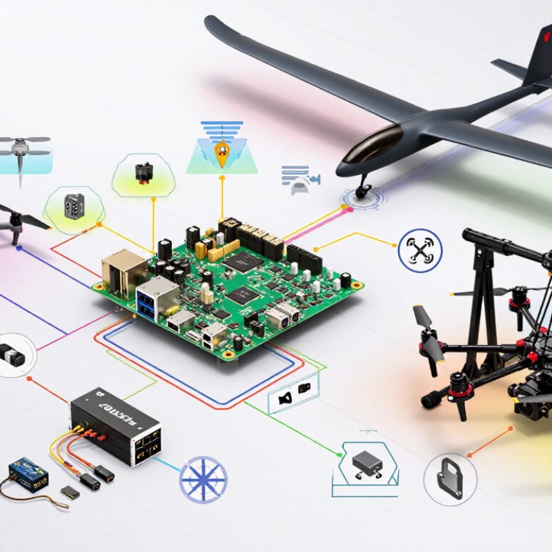
A V5+ class flight controller is the aircraft’s central control computer. It combines sensor data, pilot commands, and software decisions in real time. Its processor reads gyroscopes, accelerometers, barometers, and sometimes external positioning data. These measurements help estimate attitude, altitude, speed, and movement.
Its core function is stabilization. When the aircraft tilts unexpectedly, the controller calculates corrective motor outputs within milliseconds. It also manages navigation, flight modes, power monitoring, data logging, and communication with connected equipment. Common interfaces support GPS units, telemetry radios, receivers, range sensors, and digital motor systems. Redundant sensors can improve reliability, but they do not remove every risk. A loose connector can still end a test flight.
Choosing one requires more than checking processor speed. Inspect the sensor layout, vibration isolation, power input range, mounting pattern, and available ports. During a bench setup, verify that the controller starts consistently and reports normal sensor readings. Test each motor output without propellers installed. Safety matters.
Firmware support deserves careful attention. A capable board becomes difficult to trust when updates are unclear or configuration tools are unstable. I would also check heat during extended operation and review logged data after each test. Real installations are rarely perfect. Wiring may be crowded, calibration may need repeating, and one unused port today could become valuable later. Small details matter.
Choosing the right flight controller begins with the vehicle, not the product sheet. Define the aircraft’s mass, motor count, battery voltage, payload, and expected flight time. A compact mapping quadcopter needs different power margins from a heavy-lift hexacopter. Record peak current during a bench test, not just the motor manufacturer’s estimate. Heat matters too. After ten minutes, inspect the controller, power module, and wiring for abnormal temperature.
According to Drone Industry Insights’ 2024 Drone Market Report, the global drone market is expected to grow from about $30.6 billion in 2023 to $54.6 billion by 2030. More aircraft will perform inspection, surveying, and logistics tasks. Reliability will therefore depend on integration, not processor speed alone. Check the controller’s supported battery range, sensor redundancy, vibration tolerance, input channels, and available interfaces. Leave electrical headroom. A configuration running near its limits may pass a short test and fail in summer heat.
Field experience also suggests testing the complete airframe before final installation. Secure the vehicle, connect the intended payload, and review sensor logs during controlled motor tests. The European Union Aviation Safety Agency emphasizes risk-based operations and documented procedures in its drone framework. That principle applies here. I once underestimated cable strain on a small prototype; the flight controller was capable, but the installation was not. Reconsider the design when the payload, weather, or mission profile changes.
Choosing the best CUAV V5+ flight controller starts with its processor, sensors, ports, and expansion potential. The processor must handle navigation, stabilization, logging, and communication without noticeable delays. A faster processor offers useful headroom. That matters when the aircraft carries extra sensors or runs complex flight software. Check memory capacity too, because limited storage can restrict future updates.
Sensor quality deserves careful attention. Look for redundant inertial sensors, reliable barometric measurement, and stable compass integration. In practical bench testing, vibration isolation can matter as much as sensor specifications. A powerful sensor package still performs poorly when mounted beside a noisy motor or loose frame. Temperature changes also deserve testing. Small drift can become significant during long flights. Specifications help, but real installation conditions remain imperfect.
Ports determine how easily the controller fits your aircraft. Count serial interfaces, CAN connections, telemetry sockets, power inputs, and expansion connectors before purchasing. Leave one spare port if possible. That small decision can prevent difficult rewiring later. Expansion capability is equally important for optical flow, range measurement, external GPS, or companion computers. I have seen builds fail because every port was assigned too early. A clean wiring plan improves maintenance and reduces troubleshooting time. Still, more connectors do not automatically mean better performance. Verify voltage levels, protocol support, connector access, and physical clearance. Expect to revise your plan after the first hardware test.
Choosing the best V5+ flight controller starts with firmware support, not appearance or price. Confirm that your preferred autopilot software lists the exact board target. A similar model name is not enough. Check supported firmware versions, bootloader requirements, sensor drivers, and update procedures in current technical documentation. Release notes may reveal limits affecting navigation, logging, or peripheral connections.
Compatibility deserves a bench test. Count the available UART, CAN, I2C, and PWM ports before buying accessories. Verify voltage ranges for the power module, receiver, GPS, and electronic speed controllers. Inspect connector types and signal levels carefully. A connector can fit and still be electrically wrong. Leave room for a safety switch, buzzer, and removable storage. Small details matter.
Installation is practical engineering. Mount the controller firmly, keep its orientation accurate, and isolate it from harsh vibration without making the mount flexible. Check airflow and cable strain around the enclosure. Before powering the system, measure continuity and confirm polarity with a multimeter. Then test one peripheral at a time. I once trusted a wiring diagram too quickly. That mistake forced a complete rebuild. A written checklist would have prevented it. Firmware documentation, wiring diagrams, and verified community test reports provide stronger evidence than casual recommendations. Even after a successful setup, review sensor calibration, failsafe behavior, and log quality in a controlled environment.
Choosing a V5+ class flight controller should begin with reliability, not processing power. In field testing, inspect solder joints, connector fit, and enclosure quality before reviewing software features. A loose power lead can create more risk than a slower processor. Look for stable sensor readings during bench tests, especially after repeated power cycles.
Safety features deserve practical verification. Confirm that failsafe actions work when signal, power, or positioning data becomes unavailable. Check whether the controller records clear flight logs for later diagnosis. Redundant power input can improve resilience, but only when wiring is protected and correctly tested. Keep firmware versions documented, and avoid updating before a critical operation.
Long-term maintenance is easy to underestimate. Mount the controller away from heat, moisture, and strong vibration. Review logs regularly for rising temperature, sensor inconsistency, or unusual voltage changes. Replace damaged cables early. They are inexpensive compared with lost equipment. A clean wiring layout also makes inspections faster and reduces accidental disconnections.
I once focused too heavily on feature lists. That was a mistake. A controller may support advanced functions, yet still demand careful calibration and frequent inspection. Choose a unit with accessible documentation, replaceable connectors, and an active technical support process. Test every safety setting in a controlled environment. Never assume factory defaults match your airframe.
| Evaluation Dimension | Recommended Benchmark | Why It Matters | Verification Method | Priority |
|---|---|---|---|---|
| Processor and firmware support | A current-generation 32-bit flight-control processor with stable support for the intended autopilot firmware and release branch. | Adequate processing capacity supports sensor fusion, navigation, failsafes, logging, and future firmware updates. | Check the official hardware definition, supported firmware versions, release notes, and available parameter documentation. | Critical |
| Redundant power inputs | At least two independently protected power paths, with clearly documented voltage and current limits. | Redundancy can reduce the likelihood of total power loss caused by a single regulator, connector, or wiring fault. | Inspect the schematic and measure voltage stability under the maximum expected electrical load. | Critical |
| Power monitoring accuracy | Voltage and current readings calibrated against a trusted multimeter or power analyzer; error should remain within the project’s energy-management tolerance. | Accurate measurements improve low-battery warnings, remaining-energy estimates, and post-flight fault analysis. | Compare telemetry with calibrated test equipment at idle, cruise load, and peak load. | Critical |
| Inertial sensor redundancy | Multiple inertial measurement units with sensor-health monitoring and automatic fault isolation supported by the firmware. | Redundant sensing improves resilience against individual accelerometer or gyroscope faults. | Confirm the number of IMUs, sensor voting behavior, temperature-compensation data, and pre-arm health checks. | Critical |
| Vibration isolation | A mechanically secure mounting system that limits motor and propeller vibration without allowing excessive controller movement. | Excessive vibration can degrade attitude estimation, navigation accuracy, sensor life, and log quality. | Review vibration metrics in flight logs and inspect mounting hardware after initial hover and high-throttle tests. | High |
| Failsafe functions | Documented responses for radio-link loss, low battery, geofence breach, positioning failure, and sensor-health faults. | Predictable automated responses reduce the risk of flyaways, uncontrolled descent, and avoidable equipment loss. | Test each failsafe in a controlled environment without propellers, then validate behavior during supervised flight testing. | Critical |
| Navigation and position-source handling | Support for the navigation sensors required by the mission, including health checks and loss-of-position behavior. | Position-source quality directly affects return-to-home, waypoint accuracy, landing behavior, and autonomous safety. | Confirm supported interfaces, test satellite acquisition and position-source transitions, and review navigation logs. | Critical |
| Connector and solder-joint durability | Locking or positively retained connectors, strain relief on heavy cables, and clean, mechanically sound solder joints. | Intermittent connections are a common cause of sensor dropouts, resets, telemetry loss, and in-flight power interruptions. | Perform visual inspection, cable pull checks, continuity testing, and vibration-assisted bench testing. | High |
| Thermal management | Stable operation within the published temperature range, with adequate airflow and no direct heat transfer from high-power components. | Persistent heat accelerates component aging and may increase sensor drift or cause protective shutdowns. | Record internal temperature telemetry and inspect the controller after extended operation in the intended enclosure. | High |
| EMI and electrical-noise resistance | Clean power distribution, short signal paths where practical, twisted or shielded sensitive wiring, and adequate separation from high-current conductors. | Electrical noise can cause compass errors, communication dropouts, sensor disturbances, and unreliable telemetry. | Check sensor health during motor operation, review logs for communication errors, and inspect wiring layout. | High |
| Data logging and diagnostics | Sufficient onboard storage or reliable external logging for vibration, power, sensor status, navigation, and failsafe events. | Detailed logs make intermittent faults measurable and reduce troubleshooting time. | Verify log rate, storage capacity, download process, file integrity, and compatibility with analysis tools. | High |
| Firmware update and rollback process | Documented update procedure, parameter backup, recovery mode, and a practical way to restore a known stable firmware version. | Controlled updates reduce configuration loss and shorten recovery time after an unsuccessful upgrade. | Perform a backup and recovery drill on a spare unit before deploying new firmware to an operational aircraft. | High |
| Environmental protection | Protection appropriate to the aircraft enclosure, including dust, moisture, condensation, and cable-entry requirements. | Moisture and contamination can cause corrosion, leakage currents, connector failure, and long-term sensor faults. | Review the enclosure design, inspect conformal protection if present, and conduct controlled environmental checks. | High |
| Mechanical mounting compatibility | Mounting pattern, clearance, orientation markings, and fastener arrangement must match the airframe without stressing the circuit board. | Poor mounting can introduce vibration, connector strain, board flex, and inaccurate sensor alignment. | Confirm dimensions from the mechanical drawing and inspect clearance around connectors, cables, and ventilation paths. | Medium |
| Replacement and repairability | Replaceable cables and accessories, accessible documentation, clearly identified connectors, and a defined inspection or repair process. | Repairable systems reduce downtime, waste, and total ownership cost over repeated flight operations. | Create a spare-parts list and confirm availability of compatible cables, vibration mounts, storage media, and power modules. | Medium |
| Maintenance workload | A documented schedule covering pre-flight checks, connector inspection, log review, firmware control, and post-flight cleaning. | Consistent maintenance detects degradation before it becomes an in-flight failure. | Estimate labor per flight hour and verify that inspection tasks can be completed without removing major airframe components. | Medium |