What Is an Electronics Board and How Does It Work?

Blog

What Is an Electronics Board and How Does It Work?

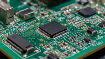
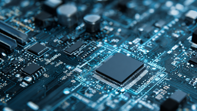
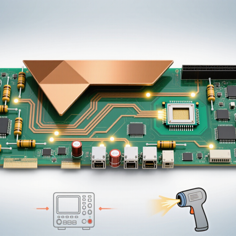
An electronics board is the working surface where components connect, communicate, and control electrical energy. It may resemble a thin green plate, but its copper traces form carefully planned pathways. Resistors limit current. Capacitors store charge. Integrated circuits process signals. Together, these parts create the behavior of a controller, sensor, computer, or household appliance.

Henry Ott, a respected electromagnetic-compatibility engineer, explains a central design principle: “The purpose of a ground is to provide a low-impedance return path for current.” This idea helps explain why an electronics board needs more than visible components. Designers must manage grounding, signal routing, heat, noise, and physical spacing. A fast digital signal can become unstable when a trace is too long. A poorly placed power component may create heat near a sensitive sensor. Small details matter.

The board does not “think” by itself. It follows electrical relationships designed by engineers and verified through testing. Power enters through connectors, travels across copper planes, and reaches functional circuits. Signals then move between chips, memory, displays, motors, or communication modules. Oscilloscopes, multimeters, and thermal cameras reveal problems that diagrams may hide.

Still, no design is perfect. A simulation can miss vibration, humidity, manufacturing variation, or a loose connector. That is where practical testing becomes essential. Understanding an electronics board means examining both its schematic and its physical behavior. It is a disciplined process, but sometimes a frustrating one. A quiet board may still hide a serious fault.
What Is an Electronics Board and How Does It Work?

What Is an Electronics Board?

What Is an Electronics Board and How Does It Work?

What Is an Electronics Board?

An electronics board is a rigid or flexible platform that connects electronic components. It usually contains copper traces, insulating layers, holes, and protective coatings. These traces act like controlled pathways for power and electrical signals. Resistors limit current. Capacitors store and release energy. Integrated circuits process information. Connectors link the board with sensors, batteries, displays, or other boards.

It is a physical system, not a thinking machine.

During a practical inspection, engineers often trace a signal from the power input to the main processing circuit. A multilayer board may hide those routes between internal copper planes. The board distributes voltage, reduces electrical noise, and maintains mechanical support. Its performance depends on material selection, layer design, solder quality, and thermal control. A small crack near a connector can interrupt an entire product.

Industry demand reflects this complexity. Grand View Research estimated the global printed circuit board market at about 89.7 billion US dollars in 2023. Another 2024 assessment from Fortune Business Insights projected continued growth through the next decade, driven by vehicles, communications equipment, medical devices, and industrial automation. Market figures differ because research firms use different product categories and forecast methods. That difference deserves attention.

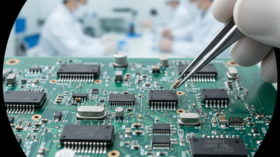
In real testing, engineers check continuity, insulation, signal quality, and heat behavior. Automated inspection helps, but it cannot replace careful failure analysis. A visually clean board may still contain hidden defects. That is where engineering judgment remains important.

What Are the Main Parts of an Electronics Board?

What Are the Main Parts of an Electronics Board?

An electronics board is a flat platform that connects and controls electrical parts. Its foundation is the substrate, often made from layered insulating material. Copper traces run across this surface like narrow roads. They carry power and signals between components. Solder pads provide small landing areas for component leads. A protective solder mask covers unused copper and helps prevent accidental connections.

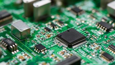
The main components include integrated circuits, resistors, capacitors, diodes, and connectors. An integrated circuit performs control or processing tasks. Resistors limit current and divide voltage. Capacitors store small amounts of electrical energy and reduce unwanted voltage changes.

Diodes guide current in one direction. Connectors link the board to sensors, batteries, displays, or other boards. Some boards also include crystals for timing and heat sinks for temperature control. Real boards are rarely perfect. A tiny trace defect can stop an entire circuit.

Tips: Inspect the board under bright light before testing it. Look for cracked solder joints, lifted pads, or darkened areas. Use a multimeter to check power and ground connections first. Keep probes steady. Measure voltage at several points, not only at the connector. I still recheck polarity because a simple mistake can damage sensitive parts. Component markings can also be difficult to read, especially on compact boards. When uncertain, compare the layout with a reliable schematic or service document. Never assume every similar-looking part has the same function.

How Does an Electronics Board Process Electrical Signals?

What Is an Electronics Board and How Does It Work?

An electronics board processes electrical signals through a carefully connected path. A sensor may produce a tiny voltage from temperature, pressure, light, or movement. That signal first reaches a conditioning circuit. Resistors can limit current, while capacitors can reduce sudden voltage changes. Operational amplifiers may increase a weak signal before further processing.

The board then sends the conditioned signal to an analog-to-digital converter. This circuit measures voltage at repeated time intervals and assigns each measurement a numerical value. A controller examines those values using programmed instructions. It might detect a temperature limit, calculate motor speed, or remove unwanted signal variations. The result can control an indicator, actuator, communication circuit, or digital display.

Signal quality depends on more than the main components. Power lines need stable voltage, and grounding paths must be planned carefully. Poor layout can allow a switching circuit to disturb a nearby sensor. On a workbench, an oscilloscope may reveal a clean waveform becoming noisy near a fast clock signal. A filter that looks correct on paper may also delay an important change. Real boards require testing under heat, vibration, load, and changing supply conditions. Some designs pass early tests but fail when wires become longer or connectors loosen. That is why engineers compare calculations with measured waveforms and revise the circuit when evidence disagrees.

How Do Electronics Boards Communicate with Other Components?

An electronics board communicates through copper traces, connectors, and carefully timed electrical signals. A processor may send a command to a temperature sensor, then receive measured data through a shared communication bus. The board converts these signals into patterns of voltage, current, and timing that other components can understand.

Common interfaces include I2C, SPI, UART, and CAN. I2C uses two signal lines and allows several devices to share the same board traces. SPI usually moves data faster, but it often requires separate selection lines for each device. UART sends data sequentially between two devices. Each interface follows rules for signal levels, clock timing, data format, and error handling. Without matching settings, communication fails.

Small details matter. A loose connector, a noisy power rail, or an overly long trace can distort a signal. Engineers use oscilloscopes and logic analyzers to inspect what actually happens, not only what the schematic predicts. A pull-up resistor may keep a shared data line stable, while shielding and grounding can reduce interference. I have found that clean diagrams can hide messy behavior on a real board. A sensor may respond correctly on the bench, then fail when a motor starts nearby. That is why testing under realistic load remains essential.

What Is an Electronics Board and How Does It Work? — How Do Electronics Boards Communicate with Other Components?

Common communication methods used by electronics boards
Communication Method Signal Type Typical Connection Data Direction Typical Data Rate or Range How It Works Common Uses Important Design Considerations
Digital GPIO Digital voltage levels Individual signal wires between pins Input, output, or bidirectional Usually used for individual states rather than a fixed data rate A board reads or drives a defined logic-high or logic-low voltage. Buttons, LEDs, relays, interrupts, and enable signals Voltage compatibility, current limits, pull-up or pull-down resistors, and protection against accidental shorts
Analog Input Continuously varying voltage or current Sensor or measurement circuit to an analog input Usually sensor to board Determined by the analog-to-digital converter and sampling rate An analog-to-digital converter samples the signal and represents it as a numerical value. Temperature, light, pressure, position, and battery monitoring Reference voltage, resolution, signal filtering, grounding, and input protection
UART Asynchronous serial digital Transmit, receive, and common ground Full-duplex Common configurations range from 9,600 to 115,200 bits per second Data is sent in frames containing a start bit, data bits, an optional parity bit, and stop bit or bits. Debug messages, configuration links, and point-to-point module communication Both devices must use matching baud rate, data format, logic voltage, and signal ground
I²C Synchronous digital Two shared lines: serial data and serial clock Bidirectional, half-duplex bus Standard modes include 100 kbit/s and 400 kbit/s; faster modes also exist A controller addresses a selected peripheral, then exchanges data over shared open-drain lines. Sensors, real-time clocks, memory devices, and display controllers Correct pull-up resistors, unique device addresses, bus capacitance, and clock stretching
SPI Synchronous digital Clock, data-out, data-in, and one or more chip-select lines Full-duplex Often several megabits per second; the practical rate depends on wiring and device limits The controller supplies the clock and selects a peripheral before shifting data in and out. Displays, flash memory, converters, and high-speed sensors More wires than I²C, chip-select management, clock polarity and phase, and short, clean signal paths
CAN Differential digital Two-wire shared bus with termination at the ends Multi-node, message-based communication Common rates range from 125 kbit/s to 1 Mbit/s, depending on the network design Nodes broadcast message identifiers; built-in arbitration allows the highest-priority message to continue. Distributed control systems, industrial equipment, and vehicle subsystems Twisted-pair wiring, correct termination, differential noise immunity, and message priority planning
USB Differential digital serial Differential data pair plus power and ground conductors Host-controlled, typically bidirectional Theoretical signaling rates vary by USB generation, from 1.5 Mbit/s to multiple gigabits per second A host manages device detection, addressing, configuration, and scheduled data transfers. Data logging, firmware updates, human interfaces, and board-to-computer connections Connector wiring, signal integrity, power delivery limits, protocol support, and electromagnetic compatibility
Ethernet Differential digital packet communication Twisted-pair or other physical network media Full-duplex network communication Common wired links operate at 10 Mbit/s, 100 Mbit/s, 1 Gbit/s, or higher A physical-layer transceiver converts board data into network signals and back into packets received by the board. Industrial monitoring, local networks, remote control, and device-to-device data exchange Magnetics or isolation requirements, impedance control, cable quality, addressing, and electromagnetic compatibility
Wireless Radio Modulated electromagnetic waves Antenna and radio transceiver Usually bidirectional Depends on radio standard, spectrum, bandwidth, distance, and environmental conditions The transceiver modulates digital data onto a radio carrier and demodulates received signals into digital data. Remote sensors, asset tracking, control panels, and connected embedded devices Antenna placement, regulatory limits, interference, power consumption, security, and link reliability
Key point: An electronics board communicates by converting information into electrical or electromagnetic signals, transmitting those signals through a suitable interface, and interpreting the received signals using hardware and software.

Where Are Electronics Boards Used?

An electronics board is a compact platform that connects components through conductive paths. It may process signals, distribute power, or control mechanical movement. In real equipment, its role is usually hidden behind a panel or enclosure. Open a household appliance, and you may find a board near the power input, display, or motor. A small sensor board can fit inside a meter, while an industrial control board may use several layered circuits.

Electronics boards are used in medical instruments, vehicles, factory machines, communication equipment, office devices, and household products. They read inputs from switches, temperature sensors, cameras, or pressure detectors. Then, they send commands to screens, valves, motors, lights, or alarms. In a factory cabinet, one board might monitor a steady stream of data beside cooling fans and wiring terminals. In a vehicle, another board can manage lighting, safety signals, or battery information. Design choices vary with heat, vibration, moisture, repair access, and required accuracy. A board can pass a bench test and still fail after months of dust exposure. That possibility is easy to underestimate.

Tips: Check the board’s operating temperature, connector fit, and power requirements before installation. Keep airflow clear and prevent moisture near exposed circuits. During troubleshooting, inspect loose cables before replacing expensive components. Document unusual noise, heat, or intermittent behavior. These small details often reveal the real fault, though not every failure has an obvious cause.