A Hand Crimper is a compact tool designed to join terminals, wires, and connectors through controlled mechanical pressure. It appears simple, yet its results depend on precise choices. The terminal must match the wire size. The conductor must sit at the correct depth. The handles must close fully.
Electrical interconnection specialist Steve Edwards explains, “A reliable crimp begins with the correct terminal, not with force.” This principle deserves attention. Many users focus on squeezing harder, but excessive pressure can deform the terminal. Insufficient pressure can leave loose strands, weak contact, or unwanted resistance. Neither mistake is obvious at first.
So, how does a Hand Crimper work? Its shaped dies compress the terminal around the stripped conductor. One section grips the copper strands. Another section supports the insulation. The tool’s geometry creates a firm connection without solder. Some models use ratcheting mechanisms. These prevent early release and help produce consistent crimps.
The process is tactile. You strip a clean length of insulation, insert the wire, and feel the terminal settle between the dies. Then, the handles close until the mechanism releases. Small details matter.
Still, hand crimping is not foolproof. A correct-looking connection may hide damaged strands or poor alignment. That is why experienced technicians inspect the terminal, tug-test the wire, and verify the manufacturer’s specifications. This article examines the tool’s structure, operating steps, suitable applications, and common errors. It also questions a common assumption: tighter does not always mean better.
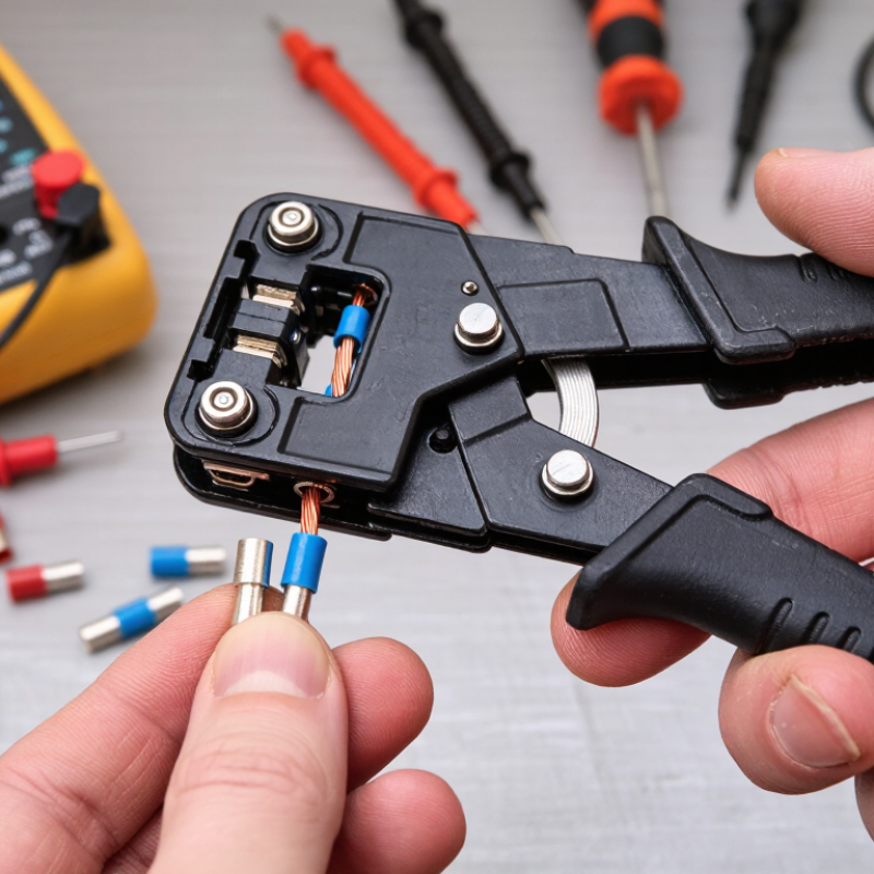
What Is a Hand Crimper and How Does It Work?
Identify the Hand Crimper’s Frame, Dies, Handles, and Ratchet Mechanism
A hand crimper joins a terminal to a wire through controlled pressure. Its frame supports every moving part and keeps the tool aligned. The frame carries the dies, pivot pins, handles, and ratchet mechanism. Without a rigid frame, compression can become uneven.
The dies are the shaped metal sections that press the terminal. Each cavity matches a specific terminal size and wire range. The handles transfer hand force through the pivots. Longer handles usually provide more leverage, but they can feel awkward in tight spaces. The ratchet controls the closing cycle. It keeps the jaws engaged until the handles reach the required position. Many ratchets also include an emergency release. That feature helps remove a misplaced terminal before full compression.
During practical use, an experienced installer checks the wire size, terminal fit, and die marking. The stripped conductor should sit fully inside the terminal barrel. The insulation should remain outside the electrical contact area. Even pressure matters. A loose crimp may pull apart, while excessive pressure can damage the conductor. The tool is simple, but mistakes are easy. It is tempting to squeeze harder when the handle feels stiff. A better approach is to inspect alignment and select the correct die first. After crimping, a gentle pull test can reveal movement. The result should look even, firm, and properly centered.
| Component or Feature | What It Is | How It Works | Typical Data or Specification |
|---|---|---|---|
| Hand Crimper | A manually operated tool used to compress a terminal, connector, or sleeve onto a wire or cable. | The user closes the handles, transferring hand force through a lever system to press the terminal around the conductor. | Common overall length: approximately 150–300 mm; intended for controlled, low-volume or field crimping. |
| Frame | The rigid body that supports the handles, pivot points, dies, and ratchet assembly. | It keeps the dies aligned and resists bending while crimping force is applied. | Usually made from stamped, forged, or machined steel; a rigid frame helps maintain consistent crimp geometry. |
| Dies | The shaped jaws or inserts that contact and form the terminal. | When the handles close, the die cavities compress the terminal to create a mechanical and electrical connection. | May be fixed or interchangeable; cavity profiles can include hexagonal, indention, oval, or trapezoidal forms. |
| Die Cavities | Individual size-specific recesses within the dies. | Each cavity matches a defined terminal or conductor-size range and limits how the metal is formed. | Typical markings may identify wire size, terminal size, or conductor cross-sectional area; compatibility must be checked before use. |
| Handles | The two lever arms held and squeezed by the operator. | They multiply hand force through their length and pivot location, moving the dies together. | Longer handles generally provide greater mechanical advantage but may require more clearance; insulated grips improve comfort and handling. |
| Pivot Pins | Pins or rivets that connect and guide the moving parts. | They provide the rotational axis for the handles and help maintain die alignment during the crimp cycle. | Require secure fit and adequate lubrication; excessive looseness can produce uneven or unreliable crimps. |
| Ratchet Mechanism | A toothed or cam-operated locking system that controls handle movement. | It prevents the handles from reopening until the dies reach the designed crimp position, helping complete the compression cycle. | Common on precision hand crimpers; many designs include a release lever for emergency opening. |
| Ratchet Release | A manual override that disengages the ratchet before the normal end of the cycle. | The operator activates the release to open the dies if a terminal is positioned incorrectly or the wrong cavity is selected. | Useful for preventing damage to the tool, terminal, or wire; location and operation vary by tool design. |
| Return Spring | A spring that assists the handles and dies in returning to the open position. | After the ratchet is released or the crimp is completed, spring force separates the handles and opens the dies. | Should provide smooth opening without excessive resistance or binding. |
| Crimping Cycle | The sequence used to form the connection. | Strip the wire, insert it into the correct terminal, position the terminal in the matching die cavity, squeeze the handles, and complete the ratchet cycle. | A completed crimp should hold the conductor securely without cutting strands or deforming the terminal beyond its intended profile. |
| Mechanical Advantage | The increase in force produced by the tool’s lever arrangement. | Handle movement is converted into higher compressive force at the dies, allowing the operator to form metal with less hand effort. | Depends on handle length, pivot geometry, die position, and the terminal material and size. |
| Quality Check | A visual and mechanical inspection of the finished connection. | The operator checks that the conductor is fully inserted, the insulation is supported where intended, and the terminal is not cracked or excessively flattened. | The correct die, terminal, wire size, and specified crimp height or pull-test requirement should always be used for the application. |