What Is an SMT Reflow Oven and How Does It Work?
An Smt Reflow Oven is a controlled thermal system used to attach surface-mount components to printed circuit boards. It heats solder paste until the alloy melts, then cools it into reliable electrical and mechanical joints. Unlike a simple heated chamber, the oven uses several temperature zones, a conveyor, and carefully measured airflow. Each zone supports a different stage, including preheating, thermal soaking, reflow, and cooling. Profiles matter.
In practical production, engineers adjust the temperature profile to match the solder paste, board thickness, component density, and conveyor speed. Thermocouples attached to test boards reveal what the assembly actually experiences, not what the display merely reports. A stable profile can reduce solder bridges, tombstoning, voids, and component damage. Small errors spread. An overheated area may discolor the board, while insufficient heat can leave dull, weak joints.
This article explains how an SMT reflow oven works, from paste activation to final cooling. It also examines heating methods, zone control, nitrogen use, conveyor settings, and routine maintenance. Reliable operation depends on more than selecting a high maximum temperature. Operators must verify calibration, inspect airflow, clean residue, and review profile data regularly. Yet the process is not perfectly predictable. Different board designs can respond differently inside the same machine. That assumption needs questioning. By combining manufacturer guidance, production experience, and measurable thermal results, readers can understand the oven’s real function and make more informed equipment decisions.
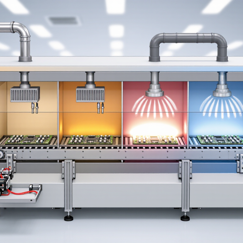
SMT Reflow Oven: Definition and Role in Electronics Assembly
An SMT reflow oven is a controlled thermal system used to solder surface-mount components onto printed circuit boards. It heats the board through several temperature zones. Solder paste melts, wets the component leads, and forms electrical and mechanical joints. The board then cools gradually under controlled conditions.
Its role in electronics assembly is more precise than simple heating. Before reflow, technicians print solder paste onto copper pads and place components accurately. Inside the oven, preheating removes moisture and reduces thermal shock. The soak zone helps stabilize temperatures across the board. The reflow zone briefly raises the assembly above the paste’s melting point. Cooling protects solder joints from excessive stress.
A reliable process depends on a measured thermal profile. Technicians attach thermocouples to large components, small pads, and board edges. They compare actual readings with the solder paste supplier’s recommended range. Conveyor speed, zone temperature, board thickness, and component density all influence results. A profile that worked yesterday may fail on a redesigned board. That is easy to overlook.
I have seen insufficient heating leave dull, weak joints. Excessive heat can damage components or lift pads. Bridging may also appear when paste volume or placement accuracy is poor. The oven cannot correct every upstream mistake. Regular profile checks, visual inspection, and process records make production more dependable. Still, operators should question stable results occasionally. “It looks fine” is not a measurement.
What Is an SMT Reflow Oven and How Does It Work?
An SMT reflow oven heats populated circuit boards through controlled thermal zones. The solder paste melts, forms reliable joints, and then cools under controlled conditions.
Representative lead-free thermal profile: The board is gradually preheated, held in the soak range, raised above the approximately 217°C lead-free solder liquidus temperature, and then cooled at a controlled rate. Actual settings vary according to solder paste, components, and PCB design.
Main Components and Temperature-Control Systems
An SMT reflow oven melts solder paste and secures surface-mount components to a PCB. Its main components include a conveyor, heating zones, cooling zones, exhaust ducts, and a control cabinet. The conveyor sets board speed. Zone heaters provide gradual thermal changes. Cooling fans reduce solder-joint stress after melting. Small details matter, especially airflow near tall components.
Temperature control follows a programmed thermal profile, usually divided into preheat, soak, reflow, and cooling. Thermocouples attached to the PCB measure real board temperatures, not only chamber air. The controller compares these readings with target values and adjusts heater output. IPC-7530C recommends profiling assemblies because component mass, copper distribution, and board thickness change heat absorption. A 20°C setting does not mean every solder joint reaches 20°C.
According to the World Semiconductor Trade Statistics 2024 Spring Forecast, global semiconductor sales were expected to reach 611.2 billion dollars in 2024, a 16.0% annual increase. More boards increase pressure for stable, repeatable reflow control. In practice, operators should inspect profile graphs, conveyor alignment, fan performance, and sensor placement. A profile may look acceptable while a hidden ground plane remains cold. That is easy to miss. Excessive peak temperature can damage components, while insufficient heat creates weak joints. The difficult part is balancing throughput with a narrow process window. Some settings still require rechecking after maintenance, seasonal temperature changes, or a new PCB layout.
How Printed Circuit Boards Move Through the Reflow Process
An SMT reflow oven turns solder paste into reliable electrical and mechanical joints. The PCB enters on a conveyor, usually with its surface flat and components facing upward. It moves through several controlled zones, not one sudden heating chamber.
The preheat zone raises the board gradually and reduces thermal shock. In the soak zone, flux activates and temperature differences begin to narrow. The reflow zone briefly pushes solder above its melting point, often around 217°C for lead-free alloys. Then, cooling solidifies each joint. Thermocouples attached to heavy copper areas and small components reveal whether the real board matches the programmed profile. It often does not. IPC’s 2023 Global Sentiment of the Electronics Industry report, based on more than 200 industry respondents, identified material costs and workforce shortages as continuing production pressures. That makes stable profiles and fewer rework cycles increasingly valuable. A practical process study should also record conveyor speed, peak temperature, time above liquidus, and void or bridging rates. A perfect-looking profile can still hide weak joints.
Tips: Place sensors near thermal extremes, such as large ground planes and connector edges. Clean the conveyor regularly. Small residues can disturb board travel. Review profiles after changing board thickness, solder paste, or component density. Operators sometimes trust old settings too much. That is where problems begin.
The Stages of Solder Paste Melting and Solidification
An SMT reflow oven heats a printed circuit board through a controlled thermal profile. The process begins during preheating, when solvents in the solder paste evaporate gradually. The board should warm evenly. Sudden heating can cause paste spattering, component stress, or uneven flux activity.
During the soak stage, the flux activates and removes surface oxides from pads and component leads. Temperature stability matters here. As the board enters reflow, the solder alloy reaches its liquidus temperature and becomes molten. Powder particles merge into a continuous liquid film. The molten solder then wets the copper surfaces and forms reliable joints around the leads. A slight pause above liquidus supports proper wetting, but excessive heat can damage sensitive components or increase intermetallic growth. I would not trust a temperature display alone. Small thermocouples attached near large ground pads often reveal colder areas that the oven sensor misses. The profile can look correct and still produce weak joints.
Cooling begins after the solder has spread and aligned the components. The liquid alloy solidifies into a metallic connection. A controlled cooling rate helps limit grain irregularities, solder cracking, and component movement. Too much cooling speed may create stress. Too little can leave joints vulnerable to shifting before full solidification. Inspectors should check solder shape, wetting, bridging, and voids. Results also depend on pad design, paste condition, board thickness, and airflow. Real production lines require measurement, adjustment, and occasional humility.