What Are the Top Advanced Circuit Types in 2026?
In 2026, an advanced circuit is defined not only by its layer count, but by how reliably it handles speed, heat, power, and space. The strongest designs connect electrical performance with manufacturability. A dense board can look impressive, yet fail if its signals distort or heat has nowhere to escape. Margins matter.
Signal-integrity educator Eric Bogatin’s work offers a practical reminder: the interconnect is part of the circuit. That principle helps explain why high-speed digital boards, RF and microwave circuits, HDI designs, rigid-flex boards, and advanced power circuits each deserve attention. Their challenges differ. High-speed designs need controlled impedance and careful routing; RF circuits demand precise geometry; power designs must manage current and temperature. Small details count, including a via transition, a copper plane, or a connector near a board edge.
This overview compares leading circuit types through their typical applications, advantages, and engineering trade-offs. It considers signal performance, thermal behavior, integration density, reliability, and production complexity—not just headline specifications. The “top” choice will depend on the device, operating environment, and manufacturing limits. Any ranking is useful, but imperfect. A design that excels in a compact medical instrument may not suit an automotive power module. The goal is to identify where each advanced circuit type fits, and what teams should verify before committing to a design.
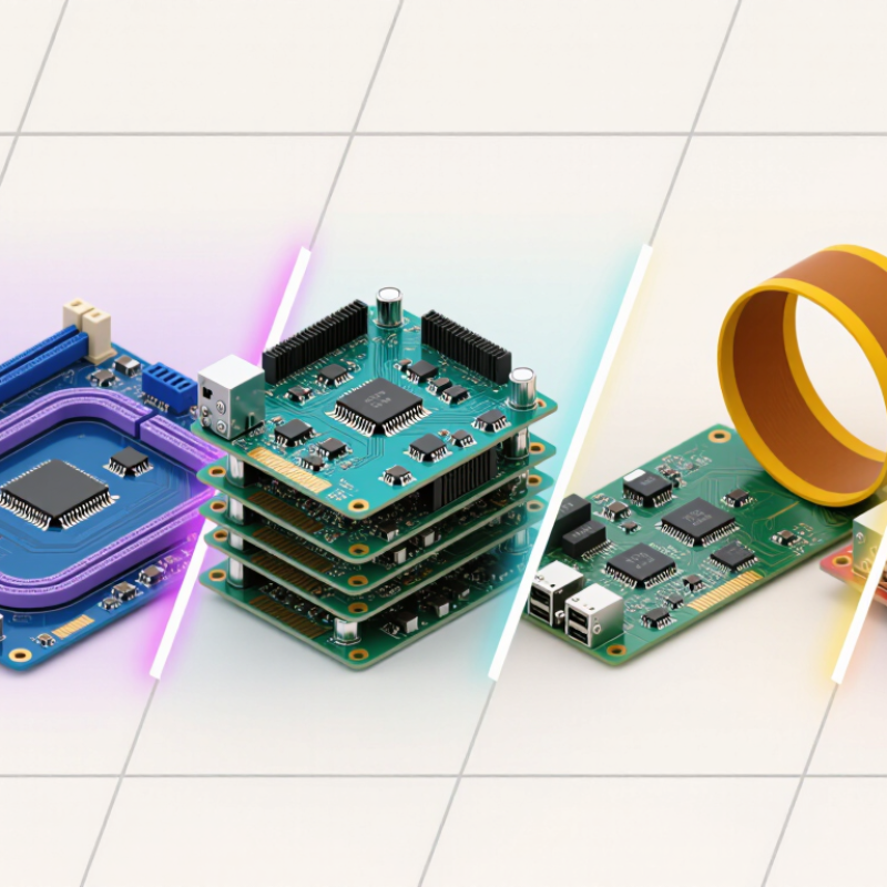
How Advanced Circuits Are Defined and Classified in 2026
What Are the Top Advanced Circuit Types in 2026?
How Advanced Circuits Are Defined and Classified in 2026
An advanced circuit is not defined by layer count alone. Designers also consider routing density, signal speed, materials, component integration, and manufacturing tolerances. Common categories include high-density interconnect (HDI), high-speed digital, RF and microwave, power, rigid-flex, and circuits with embedded components. Each solves different engineering problems.
That matters.
Classification often overlaps. A compact board may combine HDI routing with high-speed signals, while a rigid-flex design may also carry power circuitry. Engineers assess the intended use, stack-up, trace spacing, thermal load, and signal integrity before choosing a category. In 2026, packaging needs and faster data links continue to shape these choices. Still, labels can vary between teams and industries. The category alone does not prove a board will perform well.
Tips: Check the stack-up, materials, and operating requirements, not just the circuit’s name. Ask how heat leaves the board and how sensitive signals are protected from interference. A specification can look precise, yet leave practical questions unanswered. That deserves a second look.
High-Density Interconnect Circuits for Compact, Complex Devices
In 2026, high-density interconnect (HDI) circuits help compact devices fit more functions into less space. Fine traces and closely spaced pads route signals among processors, memory, cameras, and sensors without enlarging the board. Microvias—small, laser-formed connections between selected layers—save surface area and shorten routing paths. In a smartwatch, even a few millimeters can affect the case shape or battery capacity.
Many HDI boards use sequential lamination, building and connecting layers in stages. This allows designers to place components on both sides and route around crowded areas. It can also support faster signals, but only when trace geometry, materials, and stack-up are carefully controlled. A neat layout on screen is not enough. Manufacturers need consistent drilling, copper plating, and inspection to keep tiny connections reliable.
The trade-off is real. Dense layouts can trap heat, complicate repairs, and leave less room for design changes. More layers do not automatically create a better circuit. Engineers must balance routing density against thermal paths, signal integrity, and production tolerances. That balance can be easy to underestimate, especially when a prototype works well but production yields vary. In practice, small design margins often matter as much as the smallest possible footprint.
What Are the Top Advanced Circuit Types in 2026?
Representative line-and-space feature sizes by circuit technology (µm)
Smaller features can support denser routing for compact, complex devices. The ranges shown are representative industry values, not guaranteed manufacturing limits; capabilities vary by design, materials, and fabrication process.
Flexible and Rigid-Flex Circuits for Space-Constrained Designs
Flexible and rigid-flex circuits help engineers place electronics in tight spaces without adding bulky cable assemblies. A flexible circuit can fold around a camera module, hinge, or curved enclosure. Rigid-flex combines stable board sections with bendable links, creating a compact, three-dimensional layout. Fewer connectors can mean fewer potential failure points. That matters in small devices.
The design needs careful mechanical planning. A flex section that bends repeatedly needs different treatment from one folded once during assembly. Copper thickness, layer count, coverlay, and bend radius all affect reliability. Keep components and vias away from the active bend area where possible. Small details count. Even a sharp enclosure edge can concentrate stress and damage a trace over time.
Space savings are not automatic. Rigid-flex can increase fabrication complexity, and a late change to the enclosure may force a costly layout revision. Engineers should review the stack-up with the fabricator and test the actual bend path in a representative assembly. A paper model can reveal interference, but it cannot prove long-term durability. This is easy to underestimate. The best circuit type depends on the motion, heat, and service conditions the product will actually face.
Advanced IC Substrates and Embedded-Component Circuit Boards
Advanced IC substrates are becoming central to compact, high-performance electronics. Their fine routing and dense microvia networks connect small chips with less wasted board area. Shorter signal paths can help control delay and electrical noise. They also make power delivery and heat removal more demanding. A substrate is not simply a smaller circuit board.
Embedded-component circuit boards place parts such as resistors or capacitors within the board’s layers. This can free surface space and shorten connections to nearby components. Picture a tiny capacitor buried beside a processor’s power path. The layout may become cleaner, but inspection and repair become harder. That trade-off is easy to underestimate.
Design choices depend on operating conditions, manufacturing capability, and test strategy. Engineers should review material behavior, layer stack-up, thermal paths, and via placement before routing is finalized. Small details matter. A buried component that saves space may complicate failure analysis later. Not every design benefits from embedding; conventional surface-mounted parts can remain easier to change and verify. In 2026, the strongest circuit approach is the one whose density, reliability, and production needs align—not simply the most advanced option.